Designing my own mechanical keyboard from scratch
Introduction
Ever since I first laid my fingers on a mechanical keyboard, I was hooked. The feeling, feedback and the satisfying clack with every stroke was incredibly satisfying compare to the mushy rubber domes I was used to. It’s been almost six years since I dip my toes in this hobby. Only last year I’m started to think about designing my own keyboard. That’s when I decided, why not try building one myself from scratch? Yes, from the PCB to the case.
This blog will chronicle my journey into the world of custom keyboard building. From designing the PCB, to configuring custom firmware and lastly the keyboard case itself. This is not a tutorial but I’ll be documenting some of the steps, hurdles and the triumphs along the way so you can get a grasp on how to start designing your own keyboards.
Design Decisions
So the first things that have to be decided is the keyboard layout. I recommend to use KLE to design your layout. This is a useful tool that allow you to create any imaginable layout you can think of. I am a fan of Function Row Less(FRL) layout but I don’t want just the usual layout. I’m thinking that if I want to make my own custom keyboard, I better use a unique layout. So I’m thinking of adding extra keys(XT) on the left side. So it will be five more extra keys on top of the typical FRL layout. I also decided to make the top key interchangeable with a rotary encoder. This adds a touch of versatility for volume control or custom functions, depending on your preference. ANSI support only because I hate don’t use ISO.
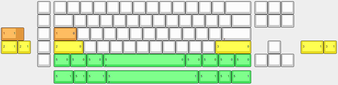 Layout
For the initial design decisions, I’ve opted to choose a comfortable 6-8 degree typing angle. More on this in the case section later. For mounting, I’m using the the tadpole pin system from GEON, because that’s what I had handy at the time. I’m making this keyboard a year ago, but if I’m doing it now, I think there are better mounting options. This will be later on my next keyboard.
For the USB connectivity, the keyboard will use Unified Daughterboard C3. This decision keeps the main PCB clean by moving the USB-C port to a separate board. This also helps me when I want to trace on my PCB later and also keep the port on the center of the keyboard. Speaking of the PCB, the PCB will be 1.6mm thickness and has and most importantly the microcontroller(MCU) must has QMK/VIAL firmware support for wired connectivity.
PCB
The most common software for designing PCB in the custom keyboard building scene is KiCad. There are useful guide on Youtube on how to start design the PCB, I recommend start with video from Noah Kiser on RP2040. But there is latest guide using STM32, which template is provided for the controller and USB port, it helps for the most part making the design decisions about routing the microcontroller. The PCB Guide from Zykrah and ai03 are also a good reading for those who want to start making their own PCBs. The frequent MCU use on keyboard PCB are ATMega32u4 and STM32. But for this project, I choose RP2040, a newer MCU which has QMK support. Besides the availability, it’s has more memory and capabilities than the ATMega and STM32. A bigger flash memory maybe useful if you want to use something like an OLED screen later down the road. Also, it’s so much cheaper at only $1 per piece compare to $5 for the ATMega32u4, at least last year on JLCPCB. I’m not sure about the availability and the prices of right now.
As you can see on the schematic below, the PCB just has simple features on it. This is my third time making PCB but its only my first time designing integrated MCU on board. This is also my learning experience for me and I’m try to keep it simple for now. If you notice, I only add an encoder and a 3mm LED for the capslock. There are no backlight because it will add complexity for me. This will be on my next project. I’m trying to keep the important features work first.
 MCU schematic
For the keys, it’s pretty simple. Just a bunch of switches arranged in rows and columns which called as matrix. The matrix is required because the MCU simply don’t have enough pins to assign to each switch. A diode also is required for each switch for the matrix to work properly. You can read more about how keyboard matrix works from the QMK docs and this great article here.
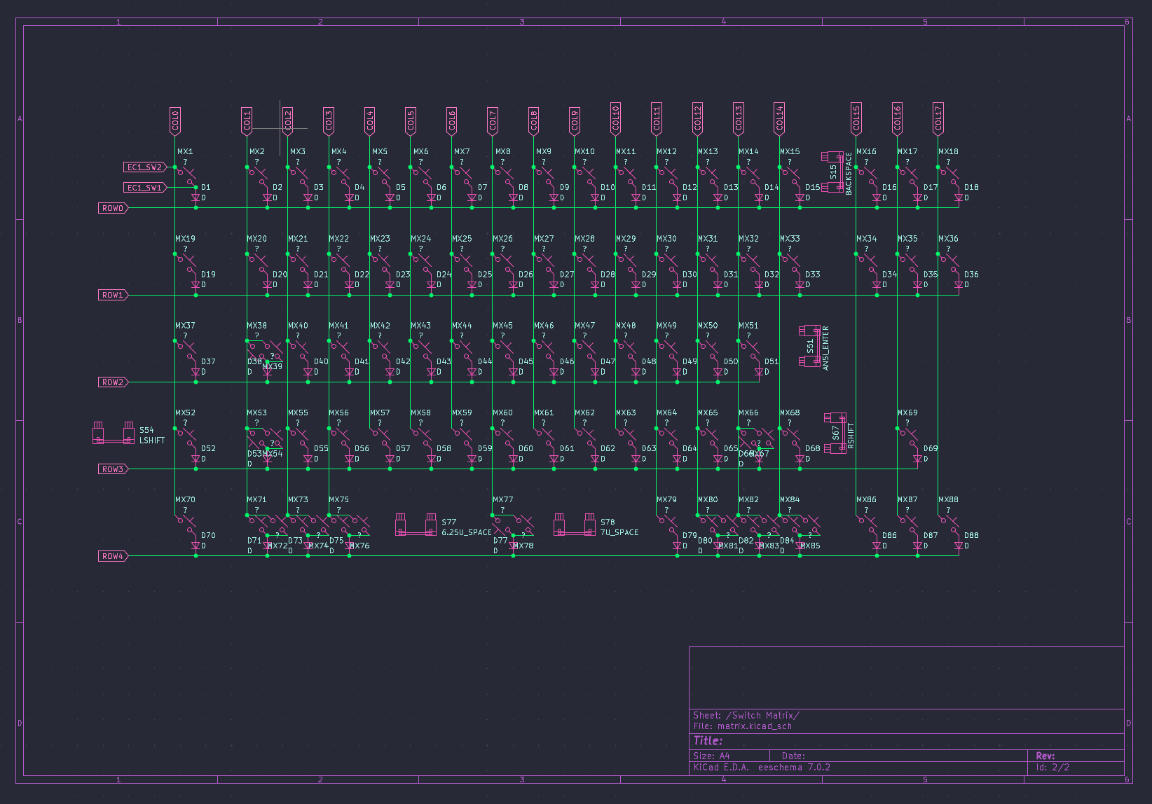 Switch schematic
Once the schematic is completed, now its time for routing the PCB. This is where the fun begins. I think this is most tedious part in designing the board. There is autoroute feature but it’s not perfect. If you want clean design, the routing should be done manually. Here I’ll share some plugins that help the work easier. The first plugins which I think essential is kicad-kbplacer which help with the keyboard’s key placing. The great thing about this plugin is it support KLE so you can import the JSON file to automatically place the keys layout. Besides that, it’s also support automatic diodes placement and track routing for switch-diodes. This plugins help you save a lot of time, I mean A LOT because you don’t have to place the keys manually.
Second, if you look closely on the PCB route below, you can see a nice clean rounded on every corner of the tracks. The kicad-round-tracks plugin can help achieve this smooth track rounding. I recommend to use this plugin in conjuction with KiCad teardrop feature, which can give teardrop-like look on the vias. My tip is try to avoid sharp corner or 90 degree bend on the track and try to use 45 degree as much as possible, this give a nicer look after the track is rounded.
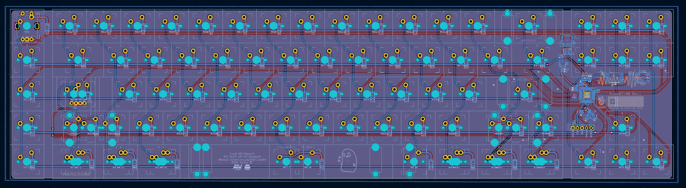 PCB Routing
After complete designing, it’s time to manufacture the board. But before that, we have to generate all the files necessary to be send to JLCPCB for the board fabrication and assembly. The KiCAD JLCPCB tools can help you generate all the files. Besides it’s also can help you search and assign the components with the JLCPCB parts database, which the result will be save in the BOM file.
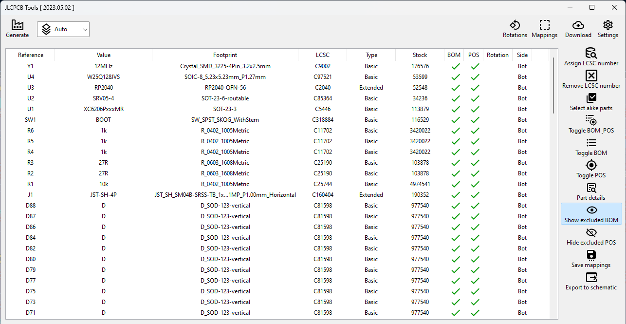 JLCPCB Tools
Manufacturing the board is fairly easy, the board gerber files will be upload to JLCPCB along with the BOM and CPL files. I have no experience in dealing with the small SMD components so I choose ‘PCB Assembly’ so I don’t have to manually solder the components later. The board fabrication, parts sourcing and the assembly all will done by JLCPCB itself. But keep in mind that this can increase the cost of manufacturing. Also, the minimum quantity you can order is 5 pieces, this can easily add up to the cost. But of course if you are adventurous and have the tools, you can choose to solder the components yourself. It’s take two weeks to ship with the shipping option I choose and cost me around 70 USD include the shipping (to Malaysia).
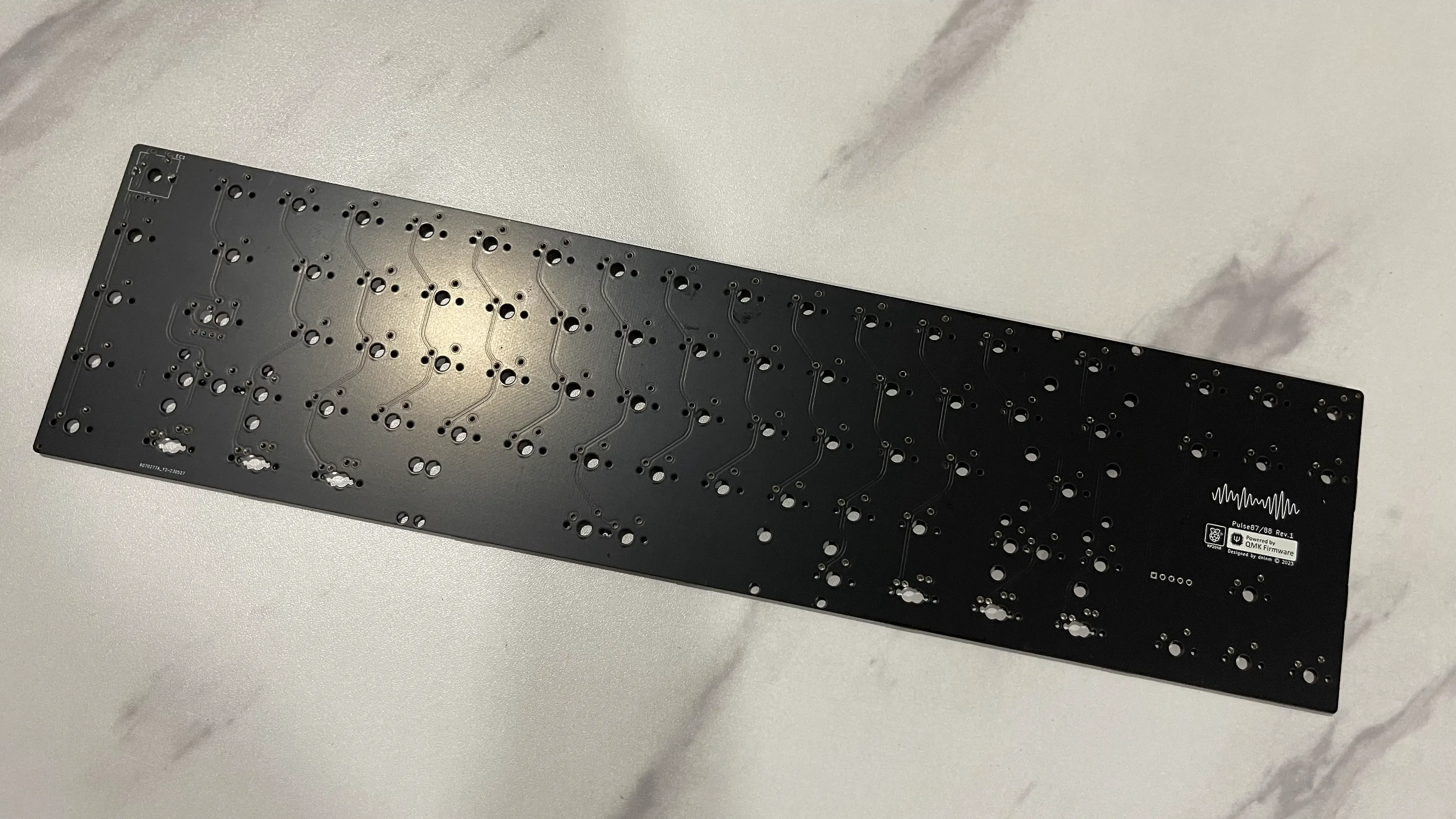 PCB Top
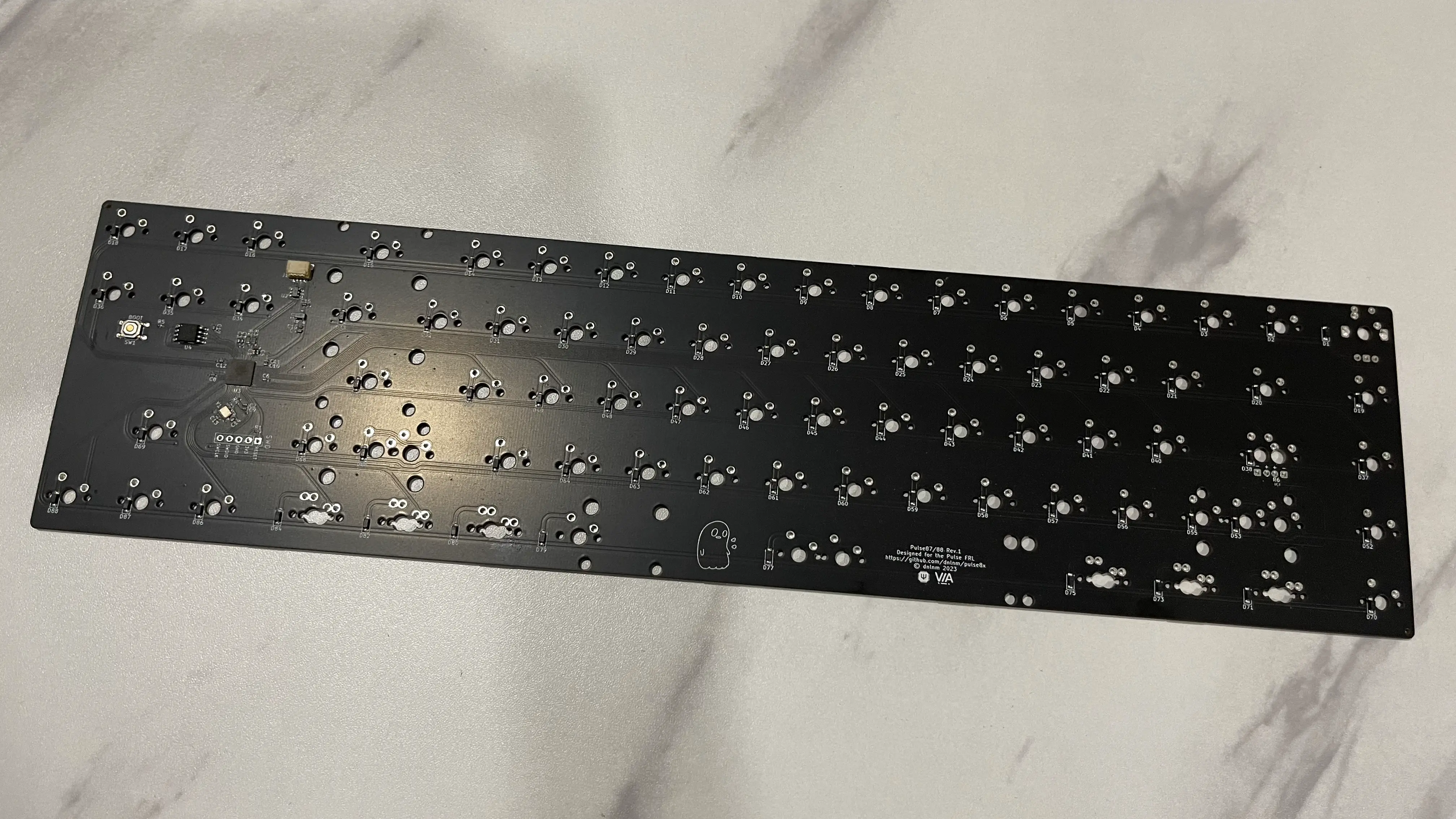 PCB Bottom
Case
This is where the fun begins. This process is where I enjoy the most. For designing the case I use Fusion 360 as it is free for personal use. There are some tutorial on YouTube you can watch. But there are also stream by some designers, where they live streaming their designing process. It is not a tutorial but you can learn a lot from the videos. I will list down some the videos at the bottom of this blog. For my keyboard I choose to make simple three pieces seamless design. We can divide it to four main parts, which are top case, bottom case, weight and plate.
The first thing that you have to do is to generate DXF for the plate at ai03 Plate Generator. Just import the JSON or raw data from KLE to the generator. There is nothing much to do here except I adding the flag to flip the spacebar stabilizer 180 degree. You can do much more customization but this is enough for this design. Then, import the DXF file into Fusion 360. Here is where you will modified the sketch to include the flex cut and the mounting points.
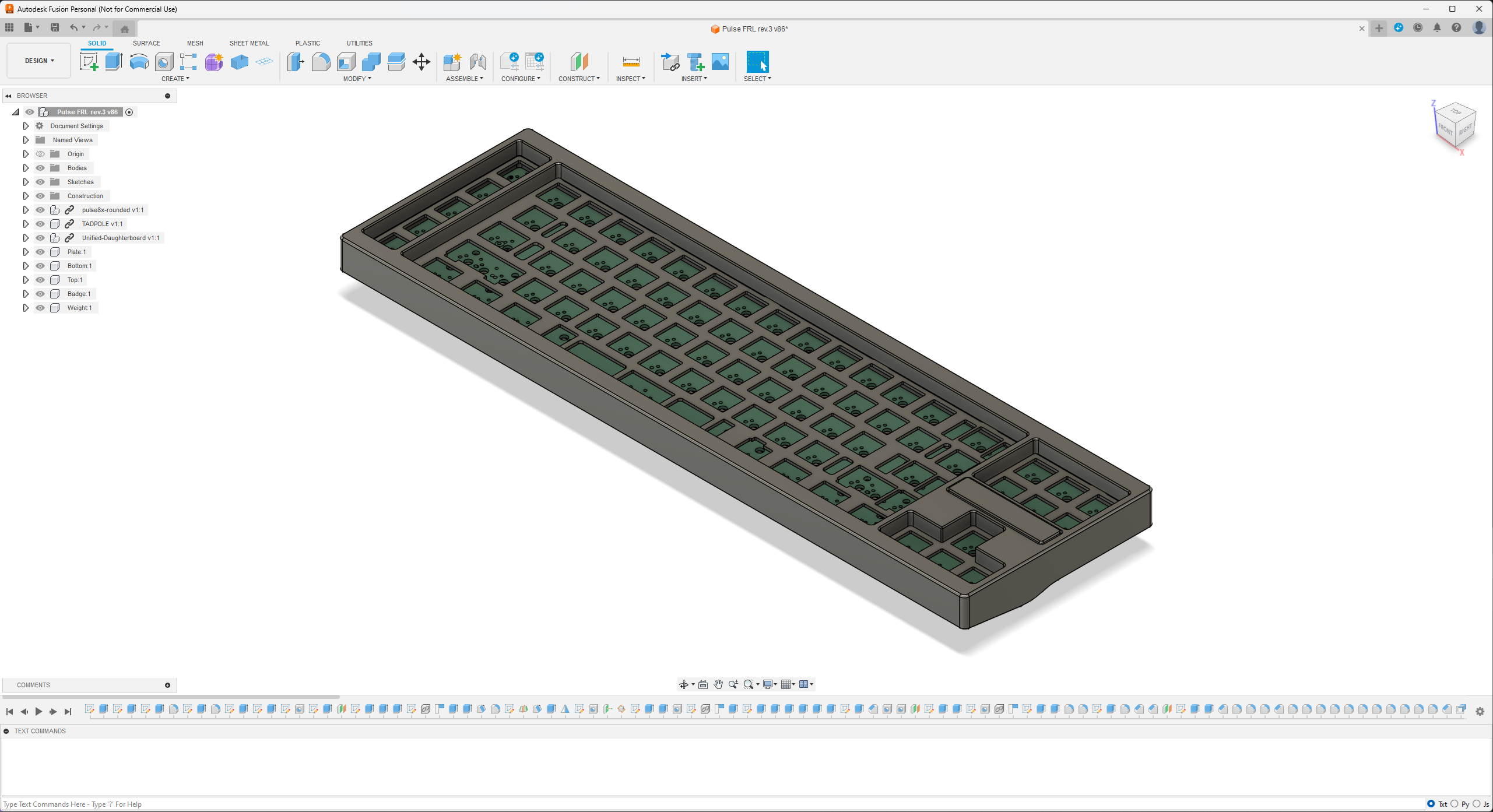 Fusion 360
Firmware
The next step is to configure the firmware for the board. The most popular and commonly used is the QMK firmware. It is an open source software that allows you to configure the keyboard.
Rendering
This is an optional step, just in case you want to render your final design.